
- #Spi serial flash programmer schematic design code
- #Spi serial flash programmer schematic design download
The (15BA:002A) and (15BA:002B) should also work, though they are currently untested. Amontec JTAGkey-tiny Olimex ARM-USB-TINY/-H and ARM-USB-OCD/-H The (VID:PID 15BA:0004) and (15BA:0003) can be used with flashrom for programming SPI chips. The 'Cable pinout' picture below shows the colors on the breakout cable. The WP# and HOLD# pins should be tied to VCC.Connect the following pins from the JTAGkey2 to the SPI BIOS chip:.You need a 3.3V voltage source - see above for details.Where to buy: Usage: More info can be found on on. And should work, if you add them to ft2232_spi.c ( untested). RushSPI v0.1 Amontec JTAGkey/JTAGkey2/JTAGkey-Tiny The can be used with flashrom for programming SPI chips. Usage: $ flashrom -p ft2232_spi:type=2232H,port=A Photos:
#Spi serial flash programmer schematic design code
The user-space source code is part of flashrom, the schematics and PCB layouts are licensed under the license and were created using the open-source EDA suite (GPL, version 2).įor more information and downloads, including a parts list, Gerber file downloads, recommended Kicad settings, and recommended PCB manufacturer settings, see.

It uses an FTDI FT2232H chip and features either a DIP-8 socket or a pinheader where jumper-wires can be attached. Where to buy: openbiosprog-spi is an Open Hardware USB-based programmer for SPI chips, designed. Where to buy: FTDI FT4232H Mini-Module The () can be used with flashrom for programming SPI chips. Module and parts FTDI FT2232H Mini-Module The () can be used with flashrom for programming SPI chips.

You have to invoke flashrom with the following parameters: $ flashrom -p ft2232_spi:type=2232H,port=A On older flashrom versions the syntax was: $ flashrom -p ft2232_spi:ft2232_type=2232:port=A Photos: All GND pins should be connected together ( pins 1 and 10 on the DLP-USB1232H, pin 8 on the SPI chip, pin 1 on the voltage regulator).The WP# and HOLD# pins should be tied to VCC! If you leave them unconnected you'll likely experience strange issues.Connect the following pins from the DLP-USB1232H to the SPI BIOS chip:.Search results can the sorted on the basis of relevance, view count, title, rating and publish date. Currently It supports 55 formats of video downloads.
#Spi serial flash programmer schematic design download
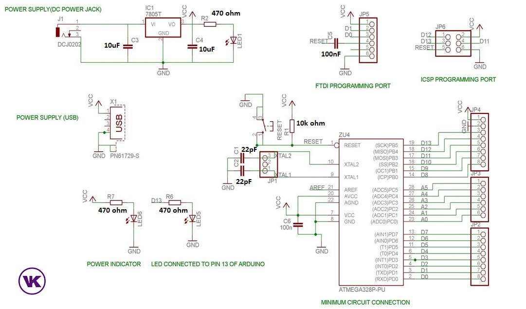
Now you can download songs, movies, episodes, trailers, clips or any Youtube video without visitng the Youtube site with hassle free controls and beautiful responsive UI. You can even search the episodes and movies and download them. 100nF and 10uF as per datasheets, but using two 10uF capacitors, or even two 47uF capacitors also works in practice) as shown in the schematics, otherwise the voltage regulator will not work correctly and reliably.

See the schematics for details (you can also for easier printing). DLP-USB1232H based SPI programmer schematics In order to use the DLP-USB1232H device as SPI programmer you have to setup a small circuit (e.g.


 0 kommentar(er)
